


Learn To TapeWire
a Dollhouse or Roombox
by Amanda Phillips
Materials Needed:
-
Cir-Kit Starter Wiring Kit CK101 which includes:
-Cir-Kit Transformer
-Lead-In Switch
-Tapewire
-Junction Splice: Cir-Kit CK1007
-Test Probe: Cir-Kit CK204
-Brass Brads: Cir-Kit CK1021 - Roombox or Dollhouse Note
- Brad Placement Tool: Cir-Kit CK1054
- Wall Plug Outlet
- 12 volt light or lamp (with plug still attached)
- Pencil
- Scissors
- Screwdriver and Hammer
- Measuring Tape
- An Extension Cord (if you are not near a power outlet this is a must)
- Magnifying Glass
- Fine Wire Strippers Note
- Small Hollow Eyelets Note
 Close-up images of materials needed.
Enlarge Picture of supplies needed.
 1. You will need to decide where to place the junction splice. The junction splice is the connection between your roombox and your real life wall socket. Where you decide to place the junction splice will determine where the cord to your power switch will be.
Enlarge Picture for planning ahead.
TIP:
It is best to place the junction splice outside of the house on the foundation, if possible. This way it does not interfere with the furniture within the dolls house. If you can't do this, try to place it nearest an outside wall and on the floor or in a corner. This is usually the easiest way to hide the connection although if it is inside the house it will be more apparent when viewing.
It is best to place the junction splice outside of the house on the foundation, if possible. This way it does not interfere with the furniture within the dolls house. If you can't do this, try to place it nearest an outside wall and on the floor or in a corner. This is usually the easiest way to hide the connection although if it is inside the house it will be more apparent when viewing.
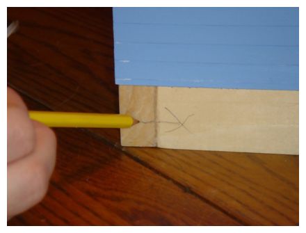
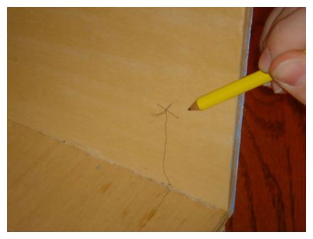
 2. Plan where you want to place your light wall plug, pencil an "X" to mark the spot on the outside.
Enlarge Picture showing a wiring path.
 3. Once you've decided where you'd like to place your lights and your junction splice and have marked both places, you can begin to layout your plans for tapewiring the roombox. Using your pencil begin drawing a path from the junction splice area to the first side edge of the roombox or dollhouse.
Enlarge Picture showing a wiring path.
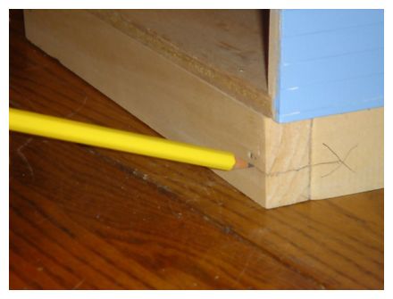
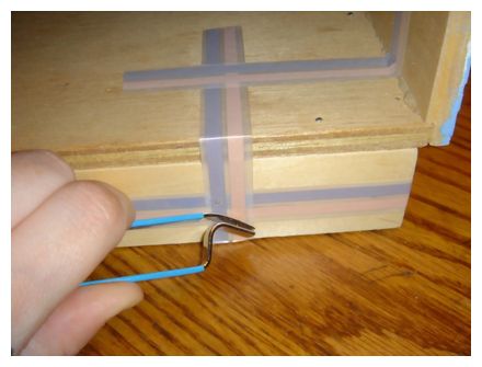
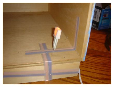
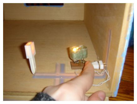
 4. Continue around any corners; maintain the straight lines with as few turns as possible, for you will need to make a connection at each turn.
Enlarge Picture showing a wiring path.
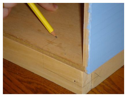
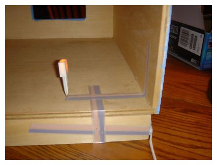
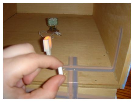
 5. Continue into the room, still in a straight line as indicated.
Enlarge Picture drawing path.
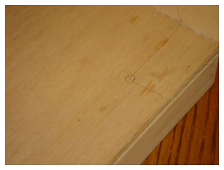
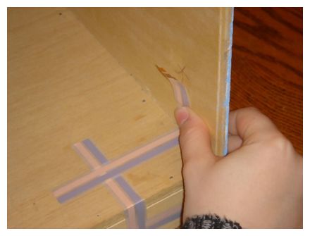
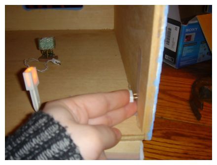
 6. Draw a circle where the lines turn. This will be important later on.
Enlarge Picture to show brad points.
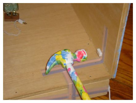
 7. Determine where you want to install the wall plug. Mark the location with an "X" that will identify your inside plug.
Enlarge Picture identifying where you will place outlet.
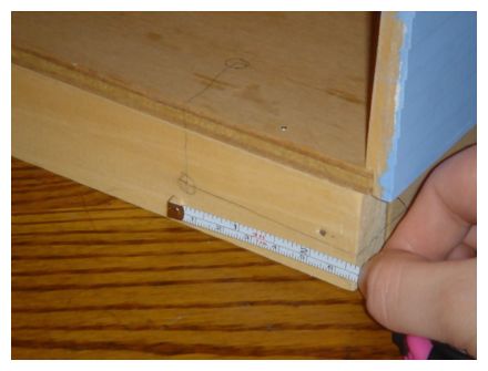
 8. Once you've drawn a path you can measure each straight line.
Enlarge Picture on where to measure.
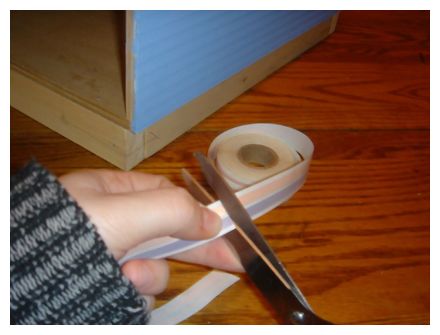
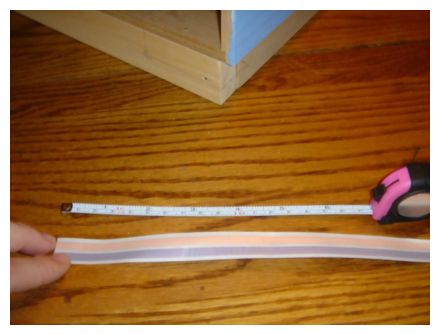
 9. Cut a length of tapewire at least 2 inches longer than your measurement. This will give some room for error.
Enlarge Picture showing cutting tapewire lengths.
 10. I usually cut mine 4-6 inches longer as it will help if there is a knot in the wood and I need to pound a nail into a different spot. Remember, the tape will go over corners, as long as it is laid in a straight path.
Enlarge Picture extra cut lengths.
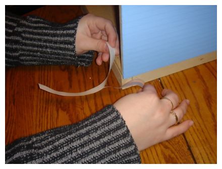
 11. Once all the lengths have been cut, remove the paper backing from the first tapewire and place the tape as smoothly as possible onto the first corresponding path drawn in pencil.
Enlarge Picture of placing the first tapewire.
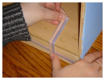
 12. Remove the backing from the second length. Remember where two pieces meet, cross them in a perpendicular manner one over top of the other. These will be your connections and will be addressed in later steps.
Enlarge Picture of second length of tapewire.
 13. Remove the backing from the third length. Again, remembering to cross the tape over the last length.
Enlarge Picture of third length of tapewire.
TIP:
Remember that spot we chose for our junction splice? It's almost time to use it. Before we do this we'll need to hook up to some power. And before we can hook up the juice, we've got to get our transformers sorted.
Remember that spot we chose for our junction splice? It's almost time to use it. Before we do this we'll need to hook up to some power. And before we can hook up the juice, we've got to get our transformers sorted.
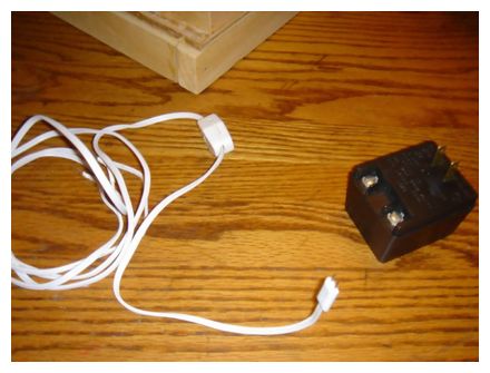
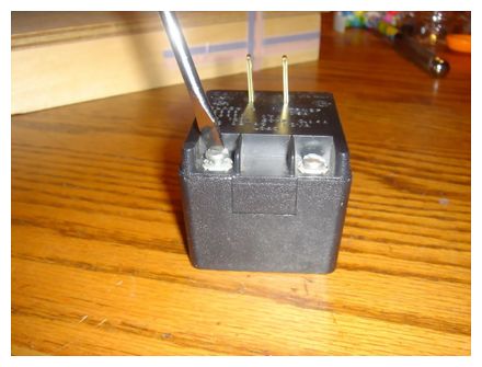
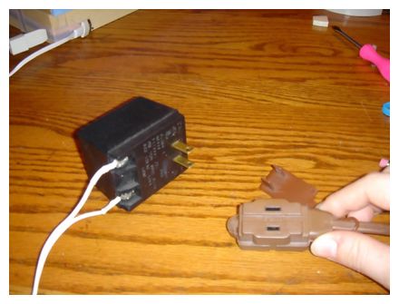
 14. Remove your transformer from the package and lay it plug side up on the table. Each transformer is a bit different, but they all work the same way.
Enlarge Picture of 12v transformer.
 15. There are two screws on the transformer and we need to loosen them (but not remove them!) using the screwdriver.
Enlarge Picture of location of screws on transformer.
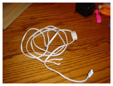
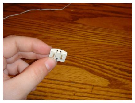
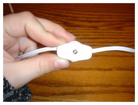
 16. Remove your lead-in switch from the package.
Enlarge Picture of 12v lead-in switch.
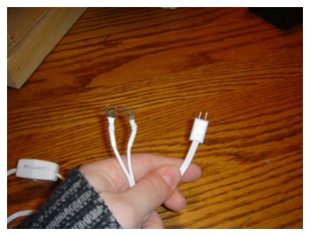
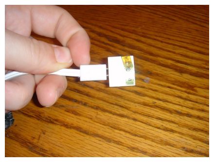
 17. This switch has two ends, one with a pair of dull pins (that look like big needle ends) and one with a split wire with two arm-like pairs of prongs on it. We're going to be using the end with the prongs.
Enlarge Picture to identifying the prongs.
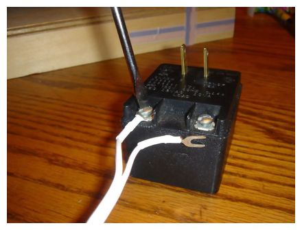
 18. Slide the left prong under the loose screw and then tighten the screw using your screwdriver (if there is a slant, make it so the wires slant upward).
Enlarge Picture to showing left wire to 12v transformer.
 19. Slide the right prong under the other loose screw and tighten.
Enlarge Picture of showing right wire to 12v transformer.
TIP:
Once the prongs are attached, they will bring electricity through the transformer when plugged into the outlet. When we plug in the main transformer be sure NOT to touch the dull pins with your fingers. It's not much of a current, but it's enough to alarm you. Please be careful when working with electricity. Make sure your extension cord is not going to be a trip hazard.
Once the prongs are attached, they will bring electricity through the transformer when plugged into the outlet. When we plug in the main transformer be sure NOT to touch the dull pins with your fingers. It's not much of a current, but it's enough to alarm you. Please be careful when working with electricity. Make sure your extension cord is not going to be a trip hazard.
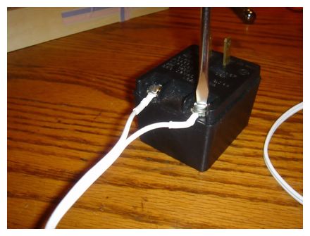
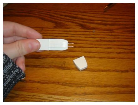
 20. Now it is time to use the junction splice. The dull prongs on the end of the lead-in switch wire are the prongs that connect into the little holes in the side of junction splice. The junction splice should come pre-packaged, attached to a piece of Styrofoam. Be careful when removing it from the foam, the prongs underneath are extremely sharp.
Enlarge Picture of Cir-Kit Concepts 12v Junction Splice.
 21. There is a small screw in some junction splices; loosen if you do have a screw in the splice. Make sure that the splice is facing the direction you would like, as the two holes in the end will connect to your transformer. Now place each prong over one strip of the tapewire, one prong into the blue coloured strip and one into the peach coloured strip.
Enlarge Picture of location of splice screw.
 22. Push firmly on the junction splice and the prongs will sink a bit into the wood. Only use finger pressure at this stage, do not hammer the splice into the wood yet.
Enlarge Picture of sinking splice into wood
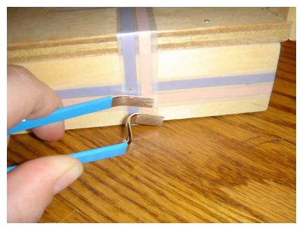
 23. Remove your Test Probe from the packaging and take off the cap. Once again, two very sharp prongs are exposed so please be careful.
Enlarge Picture of 12v test probe.
 24. Insert the prongs into your first strip of tapewire in the dollhouse or roombox. Place them just like you placed the junction splice, but a bit further along that same exact piece of tapewire.
Enlarge Picture showing placement.
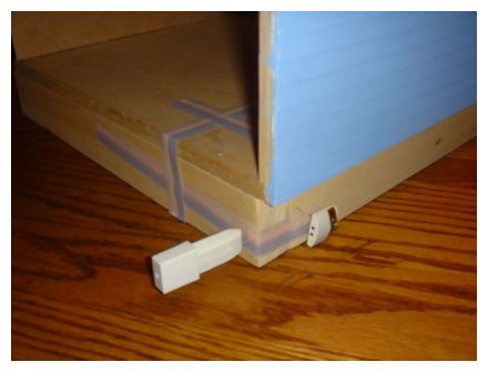
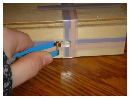
 25. Plug your lead-in switch into your junction splice (I have removed my junction splice in the photo to make this process more visible).
Enlarge Picture joining lead-in switch with splice.
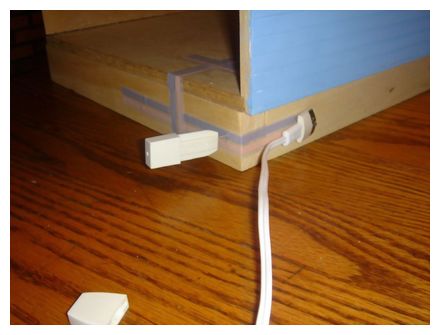
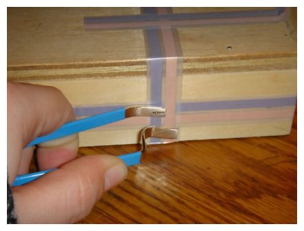
 26. You will be able to plug it in without removing your junction splice, but if it falls out don't worry, you can always push it back into the wood).
Enlarge Picture showing junction splice.
 27. Plug your transformer into your real life wall socket or into your extension cord.
Enlarge Picture showing 12v transformer
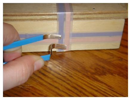
 28. Flick the switch on the lead-in switch wire to turn it from on to off and on again.
Enlarge Picture showing on/off of 12v lead-in switch.
 29. If the test probe light is blinking, your junction splice has been placed well enough to make contact with the tapewire.
If the light inside the test probe is not lit, try wiggling the test probe. Try moving the test probe farther along the strip. If it's still not lighting it could be that the junction splice is not making contact with the tapewire. Your test probe should be lit before moving on to the next step.
Enlarge Picture testing 12v current.
TIP:
At this point, if you're not getting any light into your Test Probe it could be a number of things. For one, it could be that the Test Probe is broken (this is not usually very likely), or it could be the transformer (you can test this by putting the prongs of your Test Probe onto the dull pins of the lead-in switch and flicking the switch on and off to see if the Test Probe lights up).
At this point, if you're not getting any light into your Test Probe it could be a number of things. For one, it could be that the Test Probe is broken (this is not usually very likely), or it could be the transformer (you can test this by putting the prongs of your Test Probe onto the dull pins of the lead-in switch and flicking the switch on and off to see if the Test Probe lights up).
 30. Now that the test probe is lit, unplug the lead-in switch from the junction splice. Use your hammer and center it (lightly) onto the junction splice to hammer it in. If your junction splice has a screw in it, you might wish to remove it before hammering the splice into the wall. Put the screw back in later for added stability.
Enlarge Picture to hammer in splice.
TIP:
Plug the lead-in switch back into the junction splice and test the tapewire with the Test Probe again. If it is still lit, congratulations, you're halfway to the finish!
Plug the lead-in switch back into the junction splice and test the tapewire with the Test Probe again. If it is still lit, congratulations, you're halfway to the finish!
 31. Now is the time to use our all-important brad tool, and this is possibly the most frustrating part of miniature lighting. Don't get discouraged, it may take a little while to get it right, but the most important thing is we've got power in our dollhouse already.
Enlarge Picture showing the brad tool.
 32. Unplug the lead-in switch again. Remove the Test Probe. Gather a brad nail and your brad tool.
Enlarge Picture showing how to use brad tool.
 33. Take a brad nail and place it between the prongs on the brad tool.
Enlarge Picture showing placement of brad on tool.
 34. Push the brad nail into the area where the tapewire crosses paths. Blue crosses blue.
Enlarge Picture of pushing in first brad.
 35. Press down firmly, the brad nail should partially sink into the wood.
Enlarge Picture of inserting brad nail.
 36. Carefully slide the tool back away from the brad.
Enlarge Picture of removing tool.
 37. Pulling back too quickly or too hard will pull the brad out.
Enlarge Picture showing movement of removal.
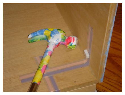
 38. Hammer the brad in the rest of the way.
Enlarge Picture showing hammered brad.
 39. Retrieve another brad. This time you will be pressing the brad into the copper/pinkish side of the tapewire, directly opposite diagonally.
Enlarge Picture showing placement of second brad.
 40. Hammer the second brad in the rest of the way.
Enlarge Picture of second brad.
 41. Now you have two brads inserted into the tapewire. Electrical current is broken at piece of tapewire; inserting the brads as shown, conducts electrical current.
Enlarge Picture showing first brads completed.
 42. Retrieve the test probe. Insert the probe a little ahead of the inserted brads, directly into the tapewire. Plug in your lead-in switch and toggle it from off to on again.
If you've got light, you've correctly placed your two (2) brads.
Enlarge Picture showing probe and testing.
TIP:
If your test probe is not lighting up, your brads might be in the wrong place. If you see sparks, immediately turn off your power! Your brads are in the wrong place and you're shorting the circuit. Remember, the brads should only go diagonally across the place where blue meets blue and copper/pink meets copper/pink. Don't put brads on all 4 cross points.
If you're still not getting any light and you've got the brads in the right places, try putting a second brad in on each location. It might be that the first brad isn't making the connection very well.
 43. Unplug the lead-in switch again. Remove the Test Probe. Move up to the next tapewire crossing. Repeat steps 33-42 above.
Enlarge Picture outlining next steps.
TIP:
Some miniaturists substitute eyelets for brads. I find that I tend to bend the eyelets and so I prefer placing the brads. Don't be discouraged if you have trouble getting the brads to sink in. It may take many practice sessions to develop a brad placing technique. If you think eyelets will work better for you, please feel free to use them.
Some miniaturists substitute eyelets for brads. I find that I tend to bend the eyelets and so I prefer placing the brads. Don't be discouraged if you have trouble getting the brads to sink in. It may take many practice sessions to develop a brad placing technique. If you think eyelets will work better for you, please feel free to use them.
 44. Now you have two brads inserted into the second tapewire crossing. You have tested the electrical current with your test probe on one side, now test on the other side.
Unplug your transformer, leaving in the test probe.
Enlarge Picture showing testing.
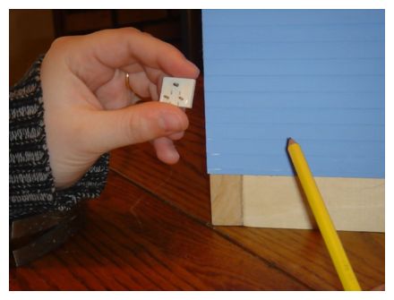
 45. Remove a wall plug outlet from the package and choose a place where you'd like the outlet for the table lamp to be. For example, you may wish to pound this in close to the place where you'll be placing a miniature table.
Enlarge Picture of wall plug outlet.
TIP:
We'll be placing an electrical Wall Plug Outlet for the table lamp (you can also use this same method for ceiling or wall lamps if you don't mind the electric wall plug outlet showing).
Placing the electric wall plug outlets allows you to plug in any 12 volt light with a male plug on it. Most lights come with male plugs already built in and they will easily plug into these wall plug outlets so you can swap your table lamps whenever you feel the need.
 46. In order to test the wall outlet connection as we place it, please turn on your transformer and then plug in a miniature light into your wall plug outlet.
Enlarge Picture of plugging in 12v transformer.
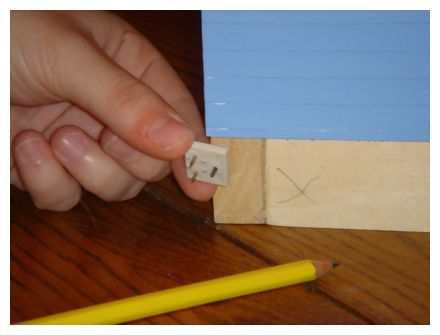
 47. The wall plug outlet works almost exactly like the junction splice does. Each prong goes into one color of the tape. One prong goes into the blue, one prong into the copper/pink side. Press the wall plug outlet pins up to your tapewire (do not push at this stage) and the light will light up. This insures that you have made good contact before moving forward.
Enlarge Picture showing how to test outlet.
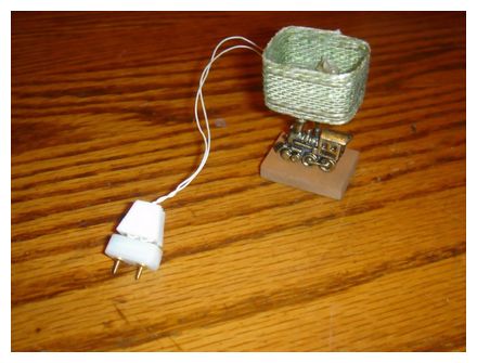
 48. Remove the light plug from the wall outlet.
Enlarge Picture of how to remove light plug.
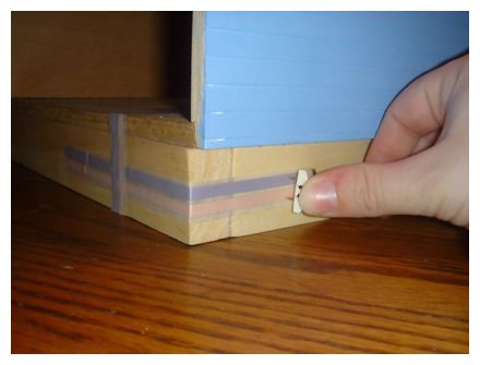
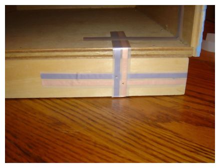
 49. Press the wall outlet in as far as you can with your fingers.
Enlarge Picture showing how to finger press outlet.
 50. Retrieve your hammer.
Enlarge Picture using the hammer.
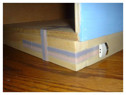
 51. Gently hammer the wall outlet into the wood. Hammering too hard can break the wall outlet.
Enlarge Picture showing how to hammer wall outlet.
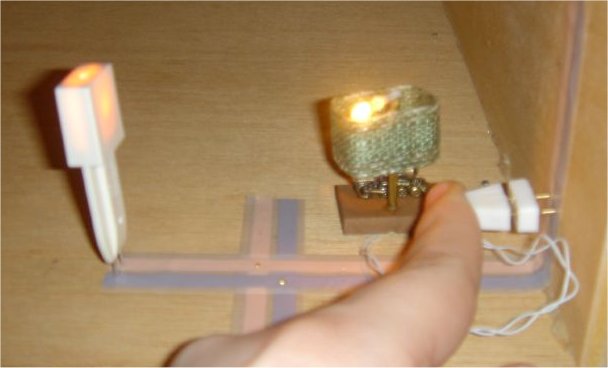
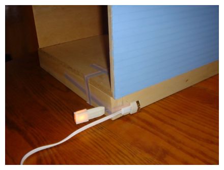
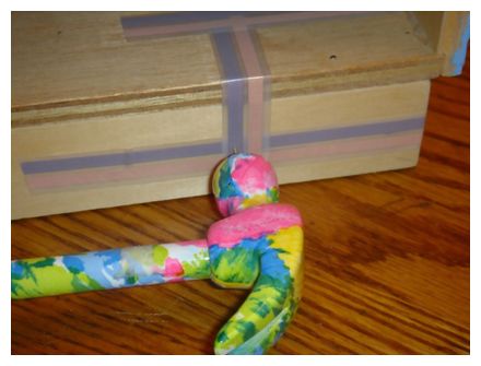
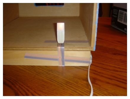
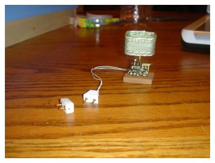
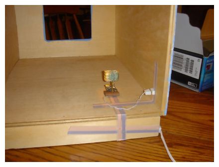
 52. Once your wall plug outlet is inserted into the tapewire, plug the miniature light into the wall plug outlet. It should light up.
Enlarge Picture showing light fixture plugged in.
TIP:
If the light is not turning on, check the bulb in your light, make sure it is screwed in tightly (if it is a screw based bulb), check that your lead-in switch is switched on, and check that the strip of tapewire the Wall Plug Outlet is plugged into is working (using your Test Probe).
If the light is not turning on, check the bulb in your light, make sure it is screwed in tightly (if it is a screw based bulb), check that your lead-in switch is switched on, and check that the strip of tapewire the Wall Plug Outlet is plugged into is working (using your Test Probe).
In the future, you can wallpaper your roombox or dollhouse over the tapewire. Then you can use the test probe to find the tapewire and then pound your outlet over the wallpaper. Some miniaturists prefer to cut a hole in the wallpaper and slip it over the plugs.
Advanced Lighting Options:
If you're comfortable with the steps we've already completed, and you want to make your dollhouse lights flush to the walls or ceilings without using any wall plug outlets.
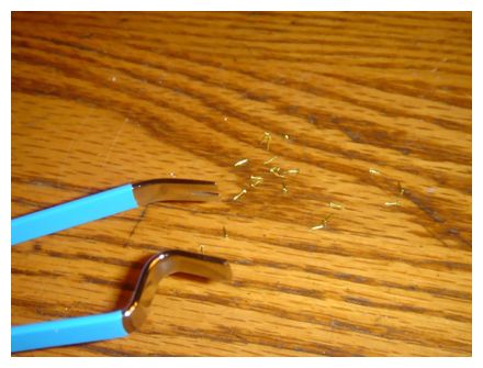
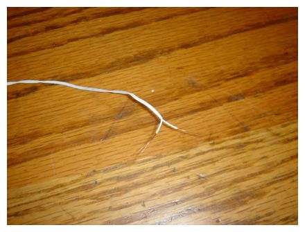
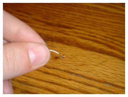
 53. Remove the plug from the light wire, either by cutting the plug off or you can pull out the plug-in pins. This will leave you with two-wires. Strip each wire on your light.
Enlarge Picture of stripping 12v wire.
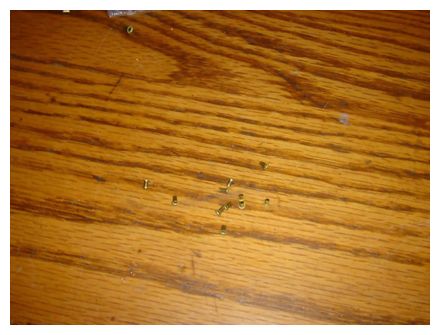
 54. Retrieve your eyelet brads.
Enlarge Picture of 12v brads.
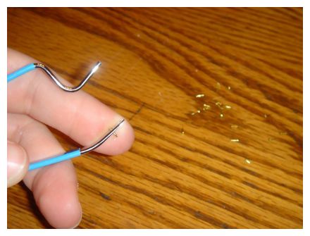
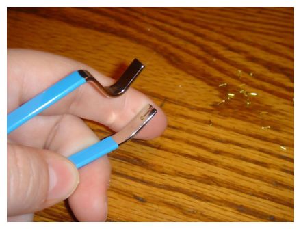
 55. Wrap each set of wires around an eyelet.
Enlarge Picture showing wrapped eyelets.
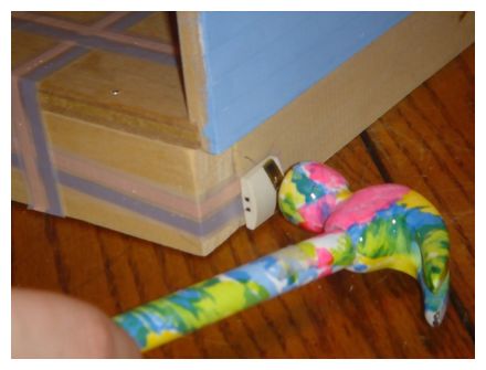
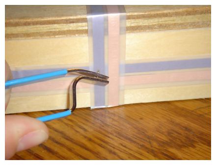
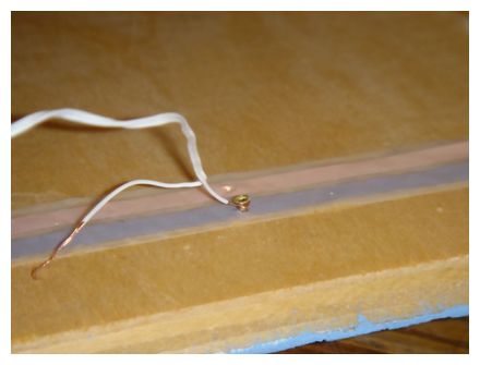
 56. Identify where you want to place your light fixture. Then insert the eyelet the same way you would a brad nail. One on each side of the tapewire. In this picture, I am placing it closest to the camera for ease of viewing.
Enlarge Picture showing how to insert outlet.
MEET THE ARTIST
 Amanda Phillips has been making miniatures since December 2005 when she found a dollhouse for sale at a charity shop and was compelled to cheer it up. She's been driving her friends and family mini crazy ever since.
Amanda is a valued member of the CDHM Forum. Visit the Galleries today.
Amanda Phillips has been making miniatures since December 2005 when she found a dollhouse for sale at a charity shop and was compelled to cheer it up. She's been driving her friends and family mini crazy ever since.
Amanda is a valued member of the CDHM Forum. Visit the Galleries today.
2007-2012 Amanda Phillips© and CDHM.org
All photographs and text appearing in this tutorial are the exclusive property of Amanda Thomas. Permission is explicitly denied for any republication of text or photographs in this article without the prior express written consent of the author.
All photographs and text appearing in this tutorial are the exclusive property of Amanda Thomas. Permission is explicitly denied for any republication of text or photographs in this article without the prior express written consent of the author.